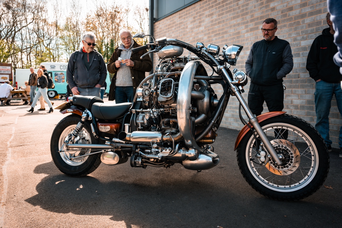
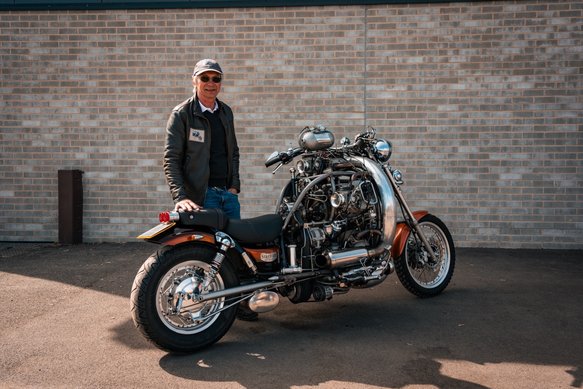
 Tim & Cheryl Oakley’s home-built 2.2-liter radial engine custom…
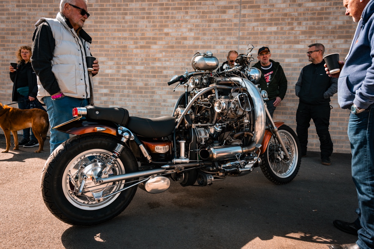
The recent KICKBACK Classic Custom Show in Great Malvern, UK, proved an absolute treasure trove of two-wheeled creativity and ingenuity. The United Kingdom has a long and storied history of home-spun engineering prowess. When it comes to motorcycles, the great Allen Millyard might be the nation’s best-known mad scientist of two wheels, but he certainly isn’t the only builder turning mind-blowing creations out of humble garden sheds and shops, often with old-school manual tools.
When we talk about “building” a bike, we typically mean the fabrication and modifications that happen around an engine, whose internals might be modified, but these blokes scratch-build their engines, too. Simon Whitelock comes to mind, with his 48-cylinder “Tinker Toy” and 7-cylinder Kawasaki “KH606,” and now Tim and Cheryl Oakley have leapt onto our radar after bringing their 2.2-liter 5-cylinder “StarFire” to KICKBACK 2026.
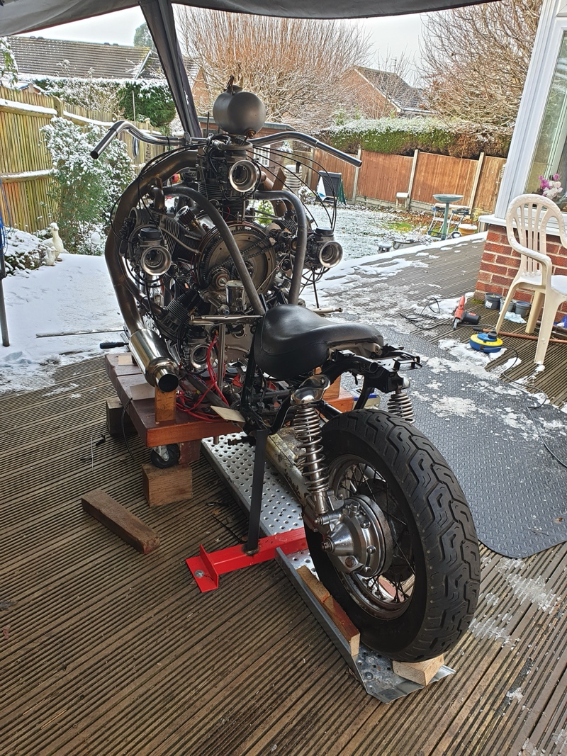
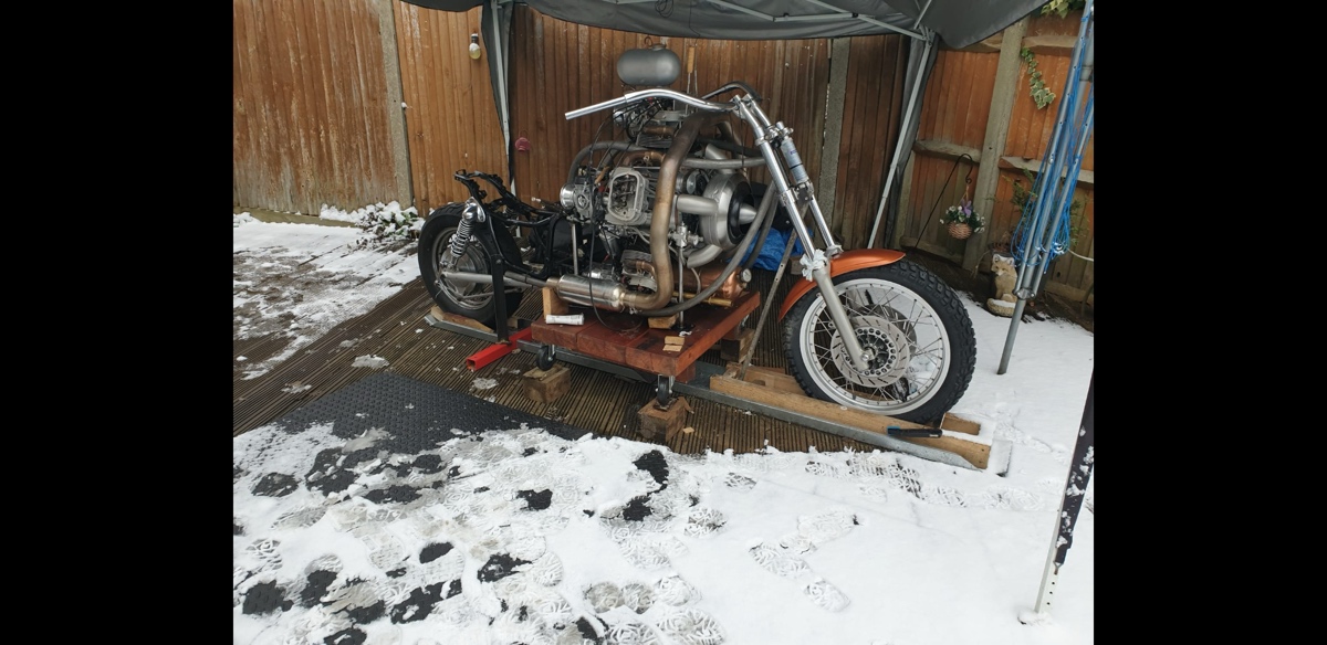
“It’s amazing what is happening in sheds around our little island. In fact Starfire was actually built outside on our decking through the brutal winter we had a few years ago in the snow.” -Tim
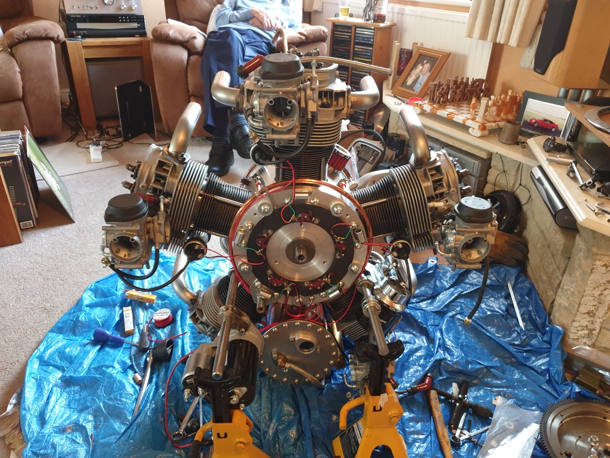
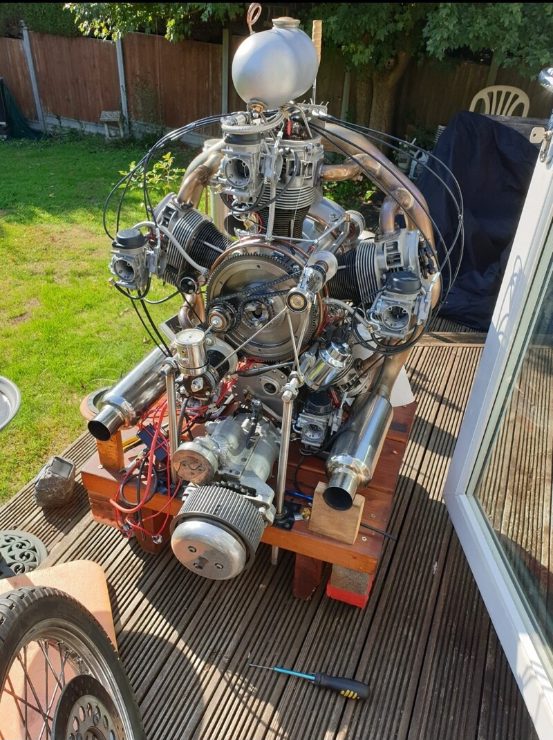
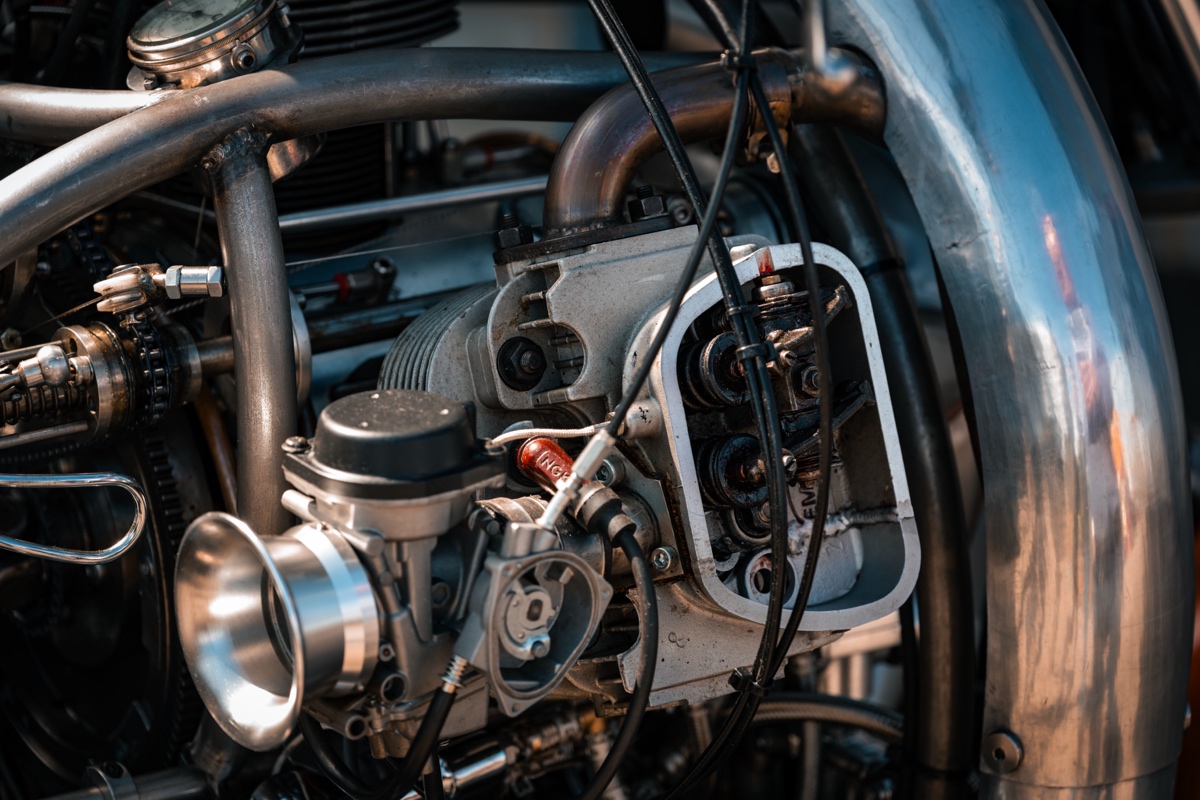
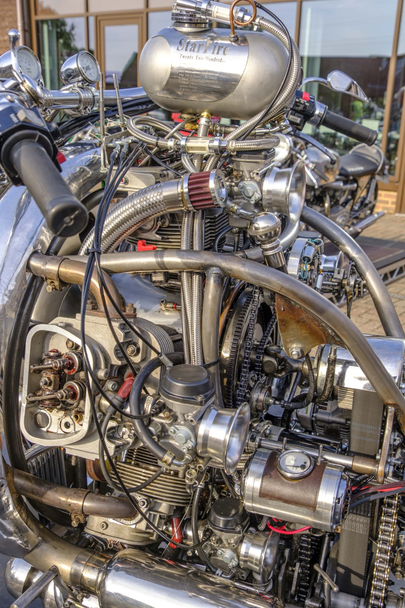
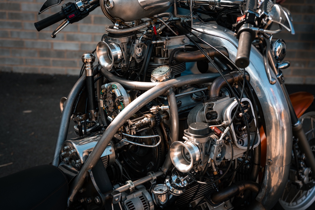
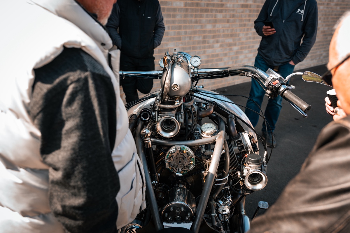
When we first saw the bike, we thought the radial engine came from an old aircraft or helicopter. In fact, Tim and Cheryl built the motor from scratch.
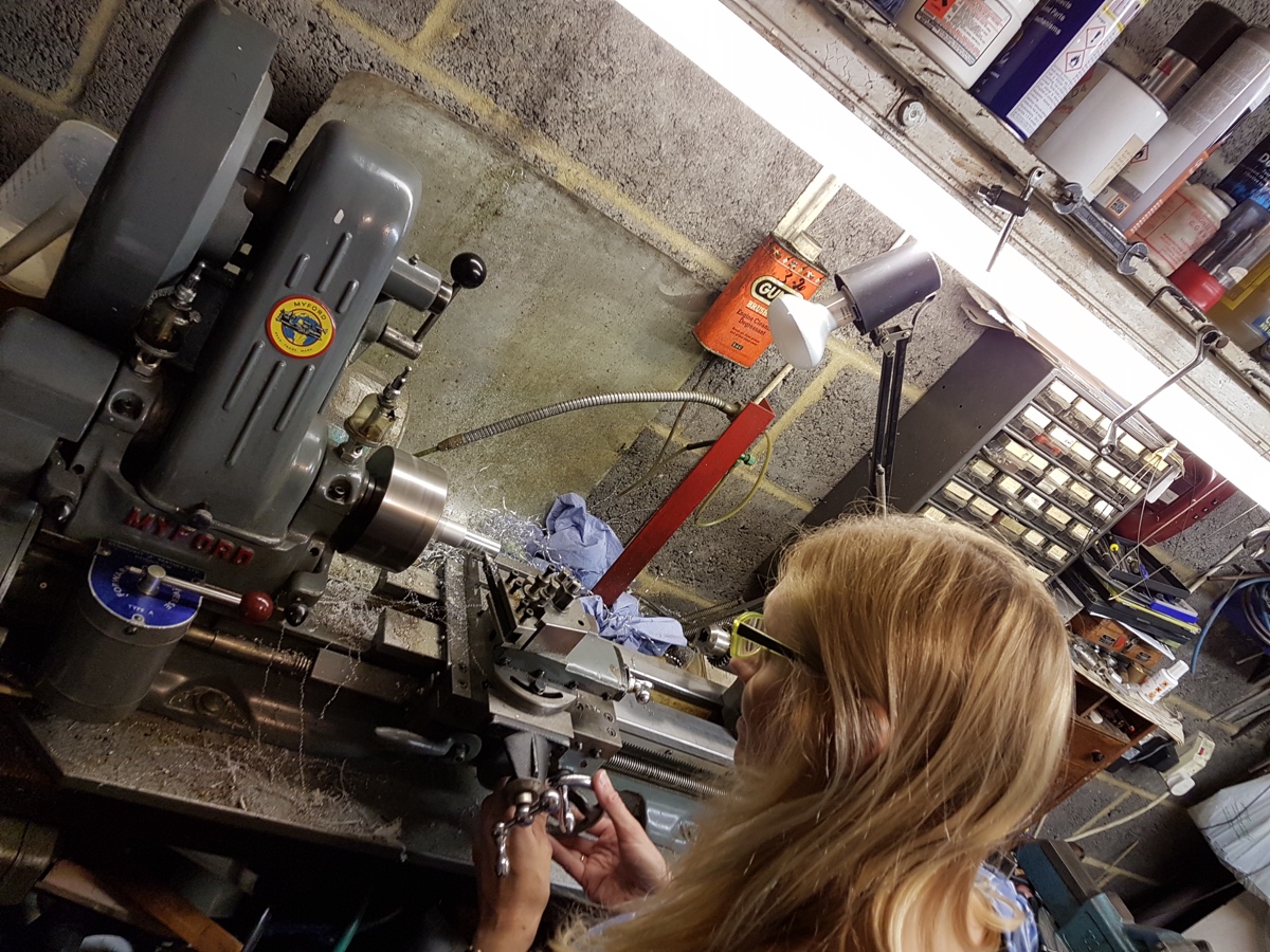
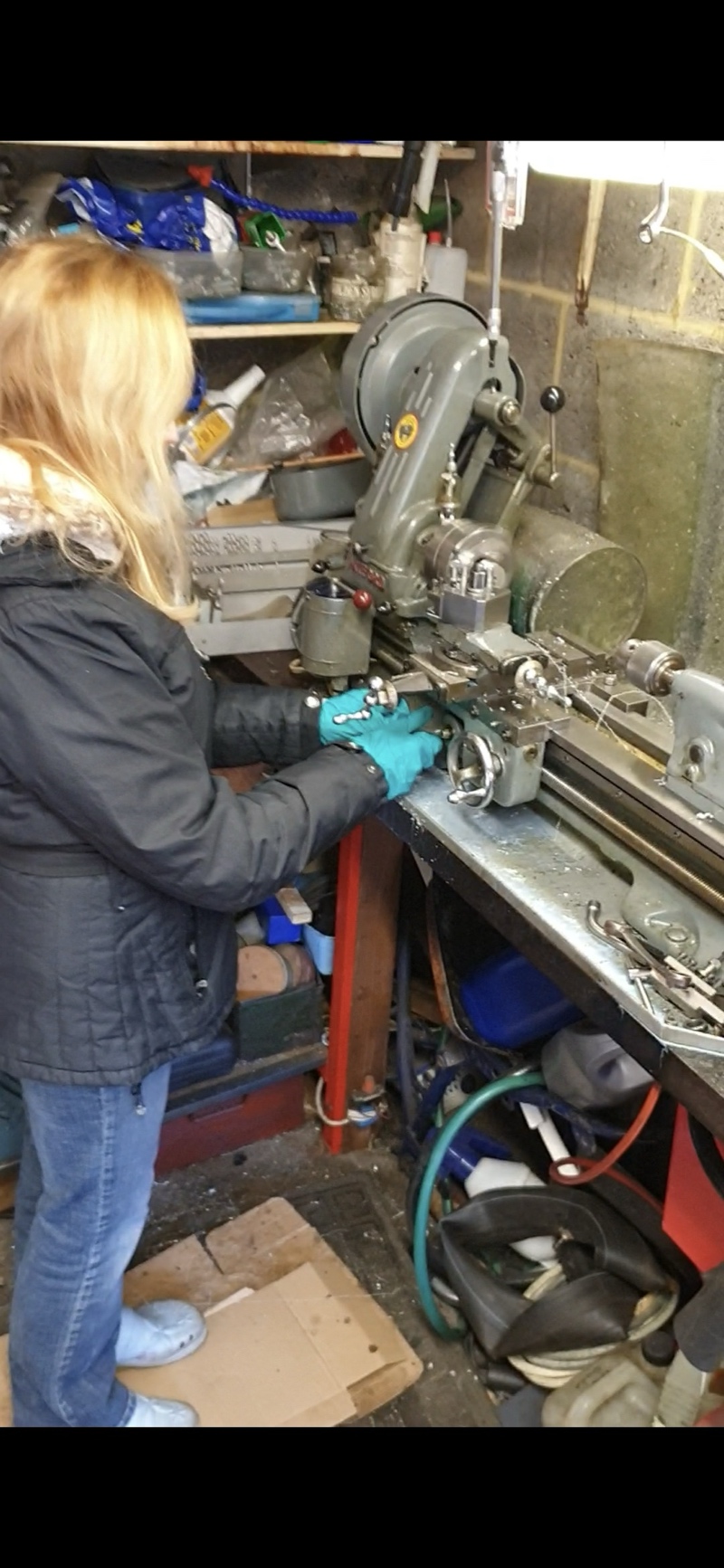
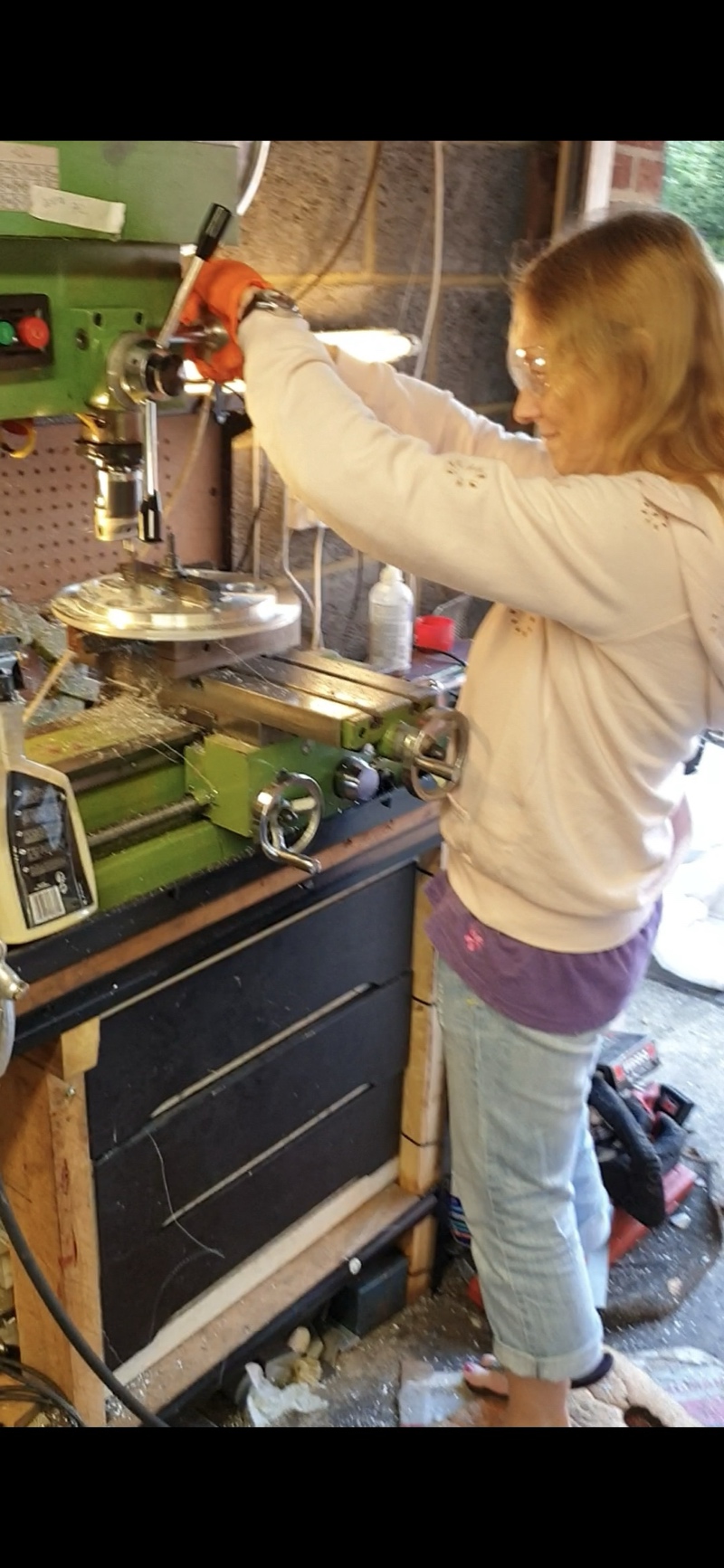
“I’m also blessed with Cheryl (my amazing wife) who loves engineering and machined parts of the engine and was involved throughout the design and build of the engine and bike. The engine spent 10 months in the front room, in front of the TV, while we designed the oil system and valve train.”
Not surprising given the level of engineering involved in building a radial engine from scratch, Tim himself is an aircraft engineer.
“747’s and Lockheed Tristar were my main aircraft, then 757, 777 and most of the executive Gulfstream types. Funnily enough, don’t work on radial engines 🤣”
Until now, we reckon! The project took them about 3.5 years, but it isn’t Tim and Cheryl’s first unusual project by any means. It seems it all started with a series of jet engines built on Tim’s father’s homemade lathe:
“Our early jet engines were built on Dad’s home made lathe. Dad made it in the early 1940’s with materials he acquired from scrap bins. In the late 80’s I stiffened the headstock and added a better cross slide, but the tail stock remained the same, a sliding bit of bar knocked onto a chuck that you leant on with a piece of wood. The jet engine took around six years to get it reliable and flying in our model plane, which became our main focus for many, many years… Then we made Hot Air Engines (Sterling engines) and also got into steam locomotives, a scale 3.5-inch model of the ‘Evening Star’ which we resurrected from the ashes and runs beautifully.”
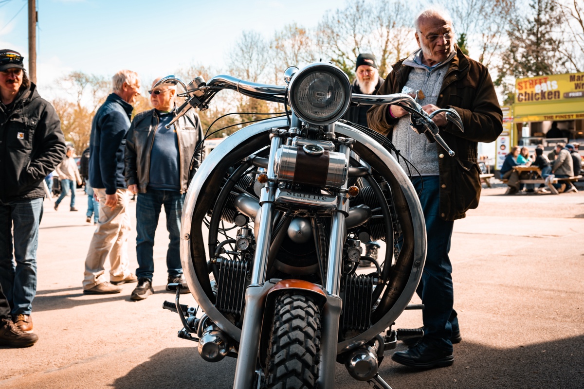
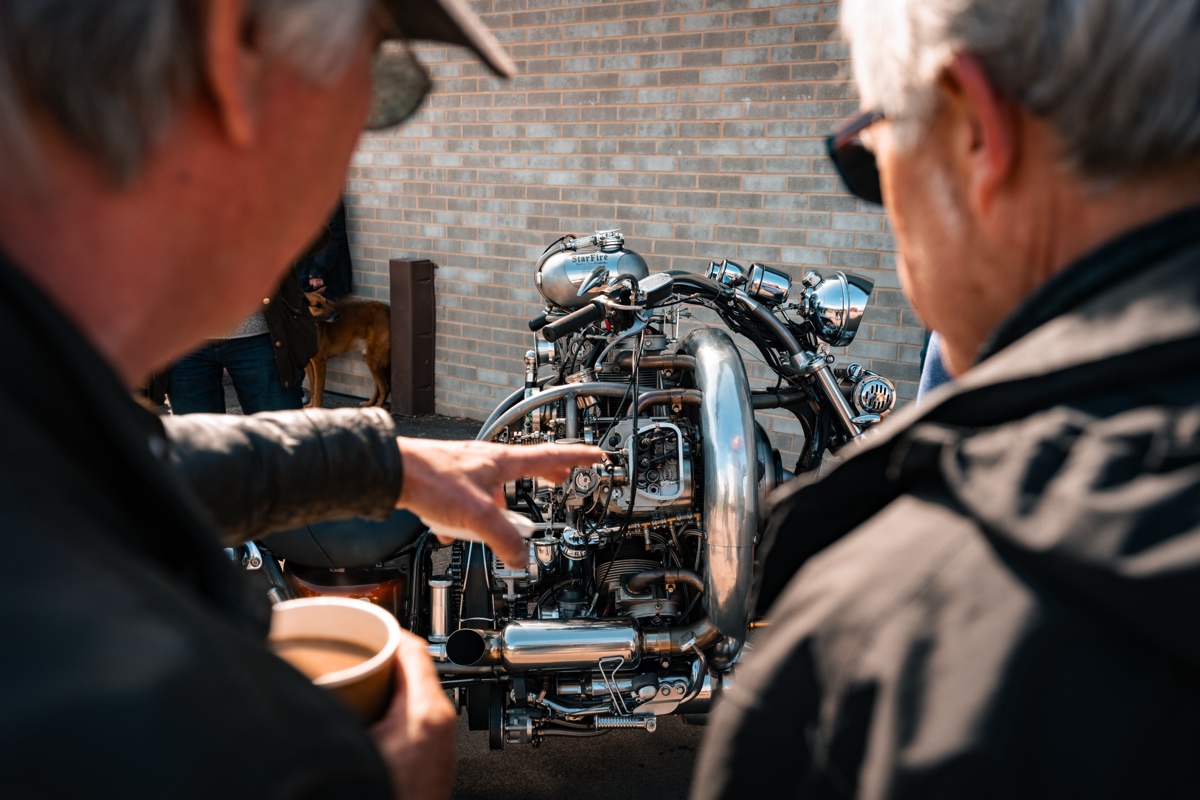
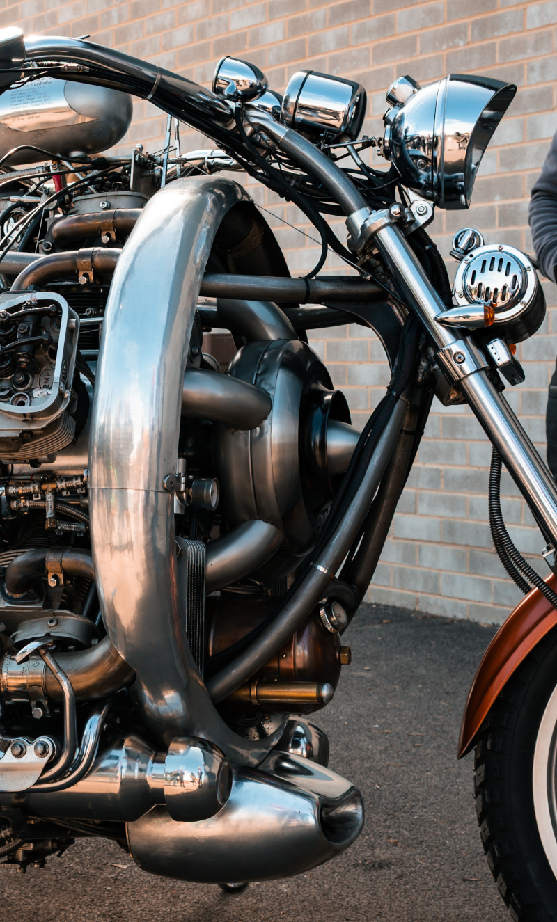
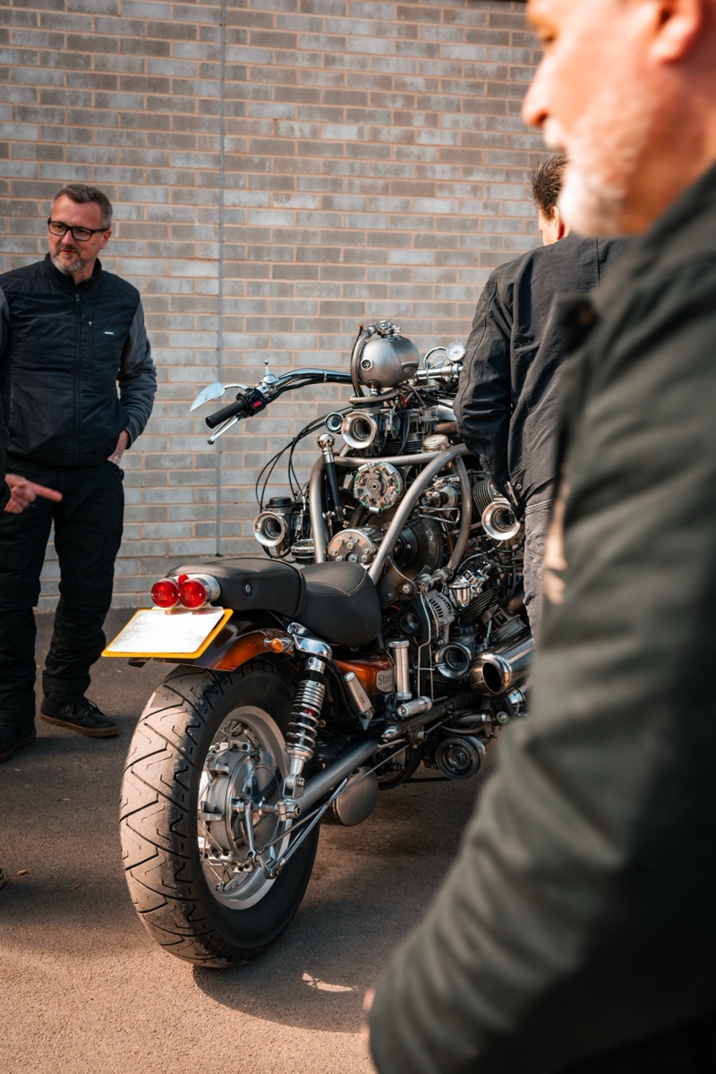
For the radial, they wanted to have as many of the engine parts as possible viewable while running. The valves and rockers are exposed, and there’s even a lighted viewing window in the crankcase! You might expect a bunch of CNC here, but nothing could be farther from the truth.
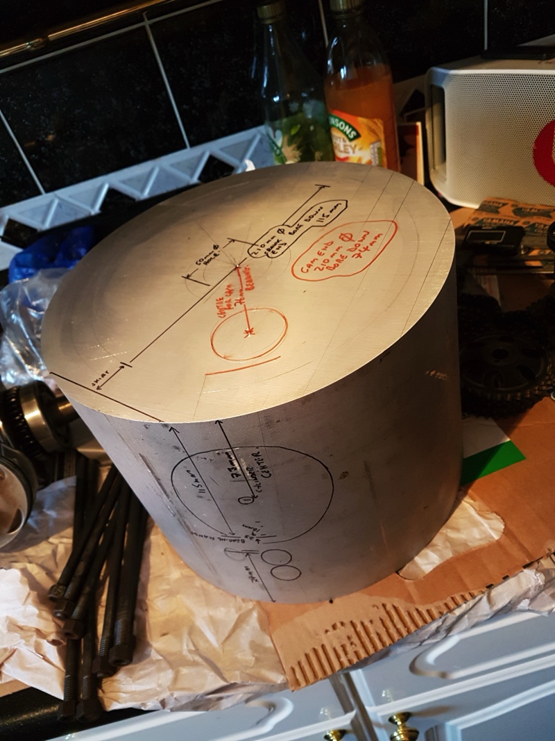
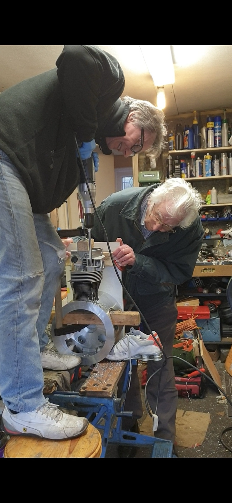
“No plans are drawn and machining is kept as simple as possible with basic tools… We use G clamps and lumps of wood, cut everything by hand with a hacksaw and I don’t do drawings, just draw on a piece before machining. We do everything by eye and do not possess precision diving heads etc, just eyeball and a pair of dividers. Everything is a challenge to overcome and satisfying when you eventually get there.”
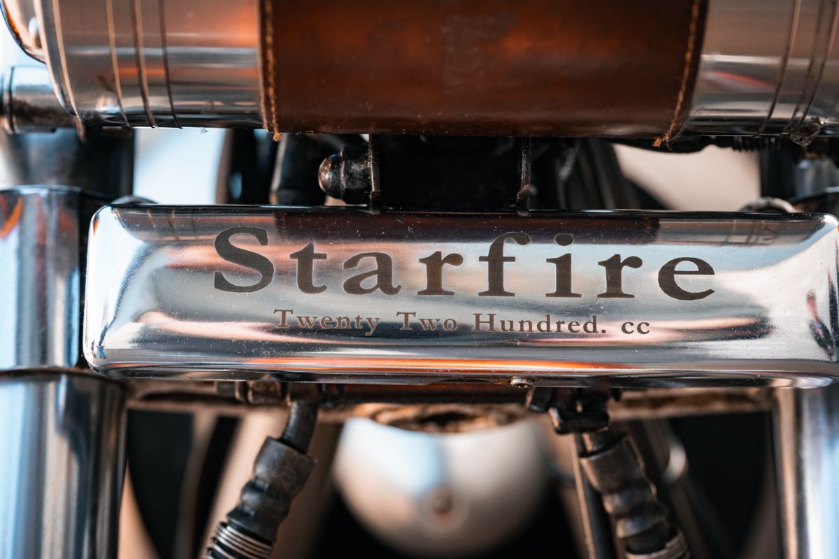
Below in the article, Tim gives us a very in-depth rundown of the different elements of the engine and bike, as well as various obstacles and challenges they had to overcome. The name “StarFire” arose after they test-fired the engine at night to see how each of the cylinders were running.
“This is why we called the engine StarFire, 5 cylinders in a star formation breathing fire. The noise was just incredible with the short exhaust stubs.”
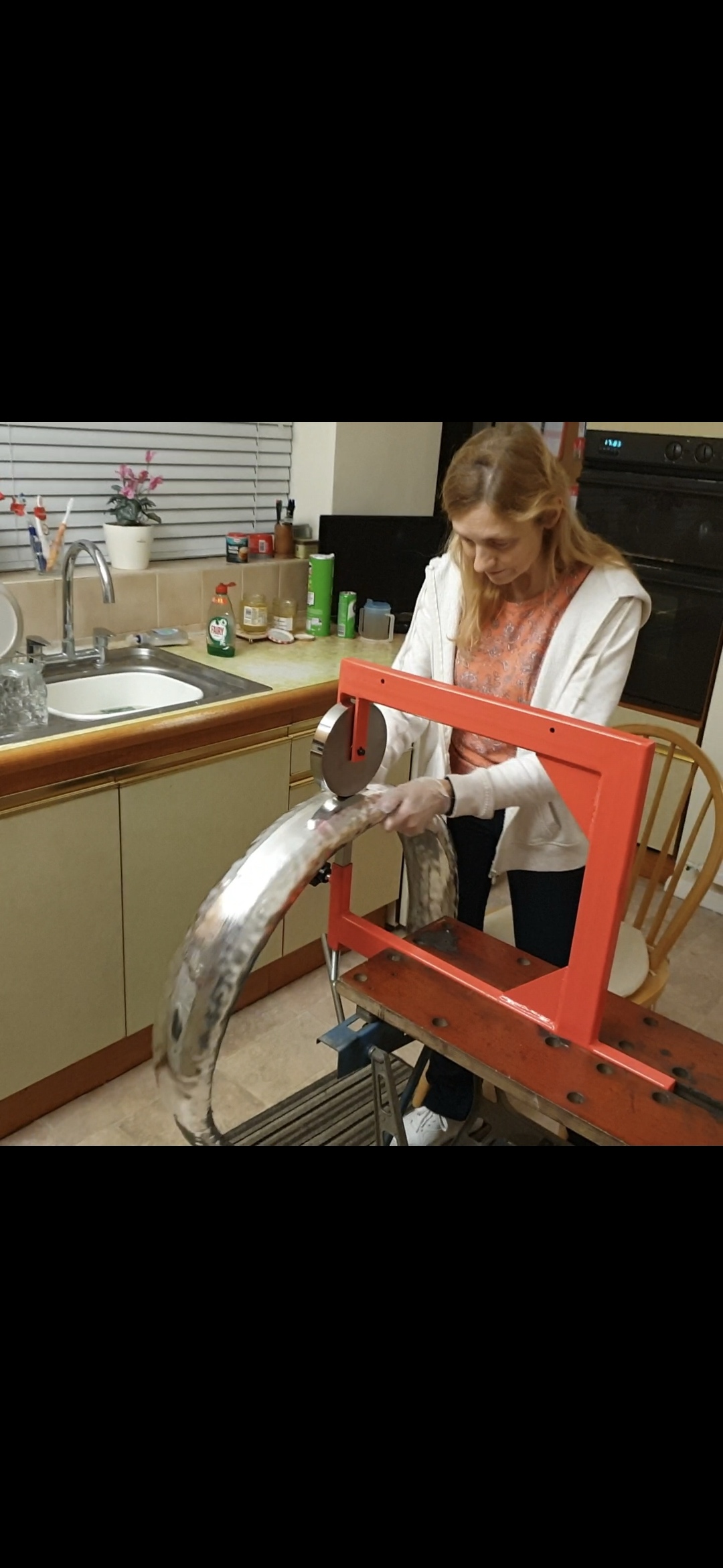
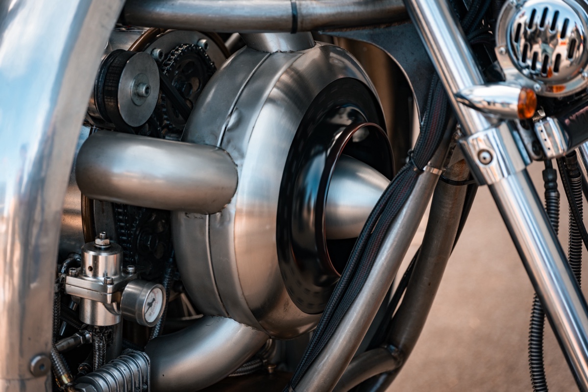
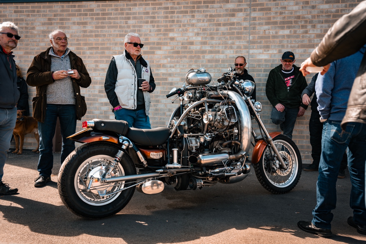
Tim says the big “ring manifold,” which is the collector ring for all the exhausts, came later to make the engine more “neighbour friendly.” Initial test runs of the bike were without the polished aluminum heat shields rolled from flat sheet on an English Wheel, which they had to learn how to do due to the “skin removal” temperatures of the exhaust system.
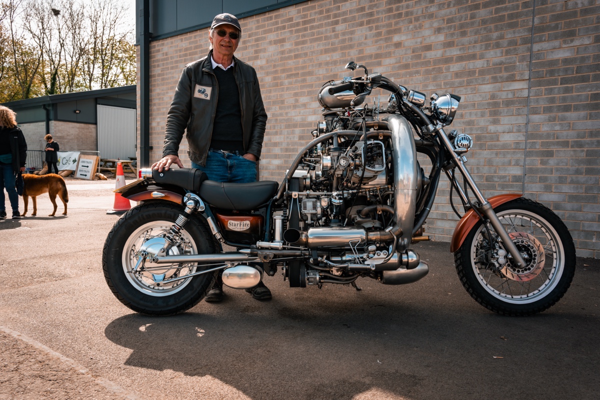
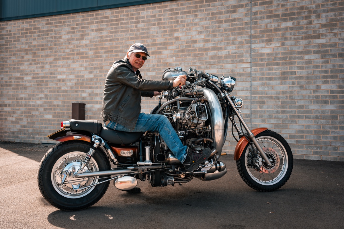
After getting the engine running, they turned to the rest of the bike — the donor was Chery’s Yamaha Virago XV750.
“Cheryl’s Virago we cut in half and new frame tubes were mandrel bent and notched by hand with a Powerfile and Starrett hole cutters in the pillar drill, to form the new frame. The bike was jigged and bolted to the decking in the back garden and took around a year to get to a stage where the bike could be driven and tested.”
Tim’s father — an engineer himself — rode foot-clutch Indians, so Tim wanted to add a hand-shift as a nod to “those amazing riders of yesteryear.” Of course, it would be quite complicated in this context. The drivetrain includes a 3-inch Harley primary pulley and a modified Ural sidecar cush-drive, and the gearbox is mounted beneath the engine with the output reversed to eliminate the torque reaction when riding.
“The 1960’s Harley 4 speeder is belt driven by the engine, the output of which is reversed through a homemade gearbox (skeletonized with side windows ) to drive the rear wheel driveshaft and bevel box by chains and sprockets. Final gearing gives 70mph at approx. 2000rpm.”
Tim says the bike gets 22 miles per gallon at 70 mph, and rides surprisingly well.
“The bike rides very well indeed very comfortable and I am very used to it now. There is so much going on with valves and distributor operations coming together to propel the machine along, with oil pumps keeping everything alive and the engine whizzing around in a confident yet slightly unusual beat that radials have, it always feels like you have been on an adventure when you arrive at your destination.”
Tim says there’s no vibration dampening at the pegs or handlebars — surprisingly, the StarFire doesn’t need it — and they don’t have any heat issues riding behind it.
“It’s like we took on a challenge and together we all pulled it off. We have riden on the coldest days through the winter and the hottest days in the summer and she has never missed a beat. When we pull up it is wonderful to chat to people. We get many questions especially about how hot it must be behind the engine, but there is no noticeable heat there. Only your right leg gets warm if you put it directly in the exhaust, the left exhaust is actually cool, yes it’s cool.”
Best of all, the StarFire stands as something of a tribute to Tim’s old man.
“My father, an incredible engineer, saw the whole project through and it was the greatest honour for me to take him on his last ride out on StarFire to his final resting place — she did us proud!”
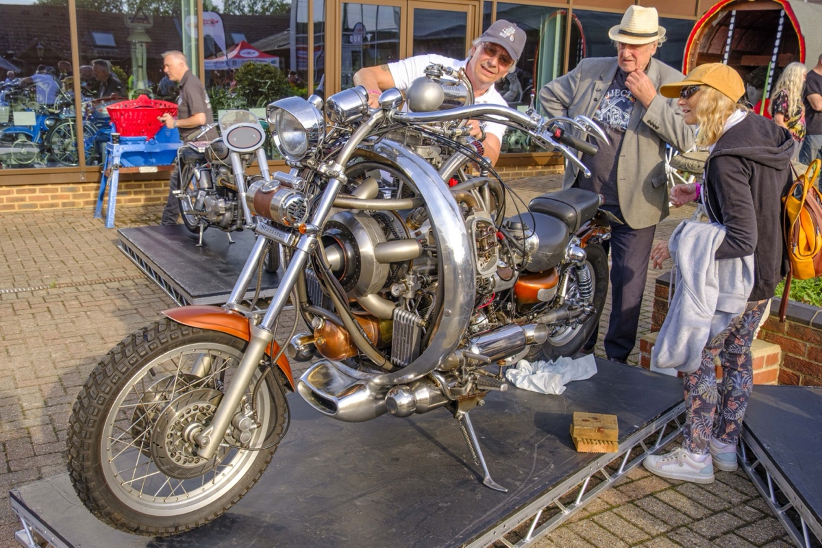
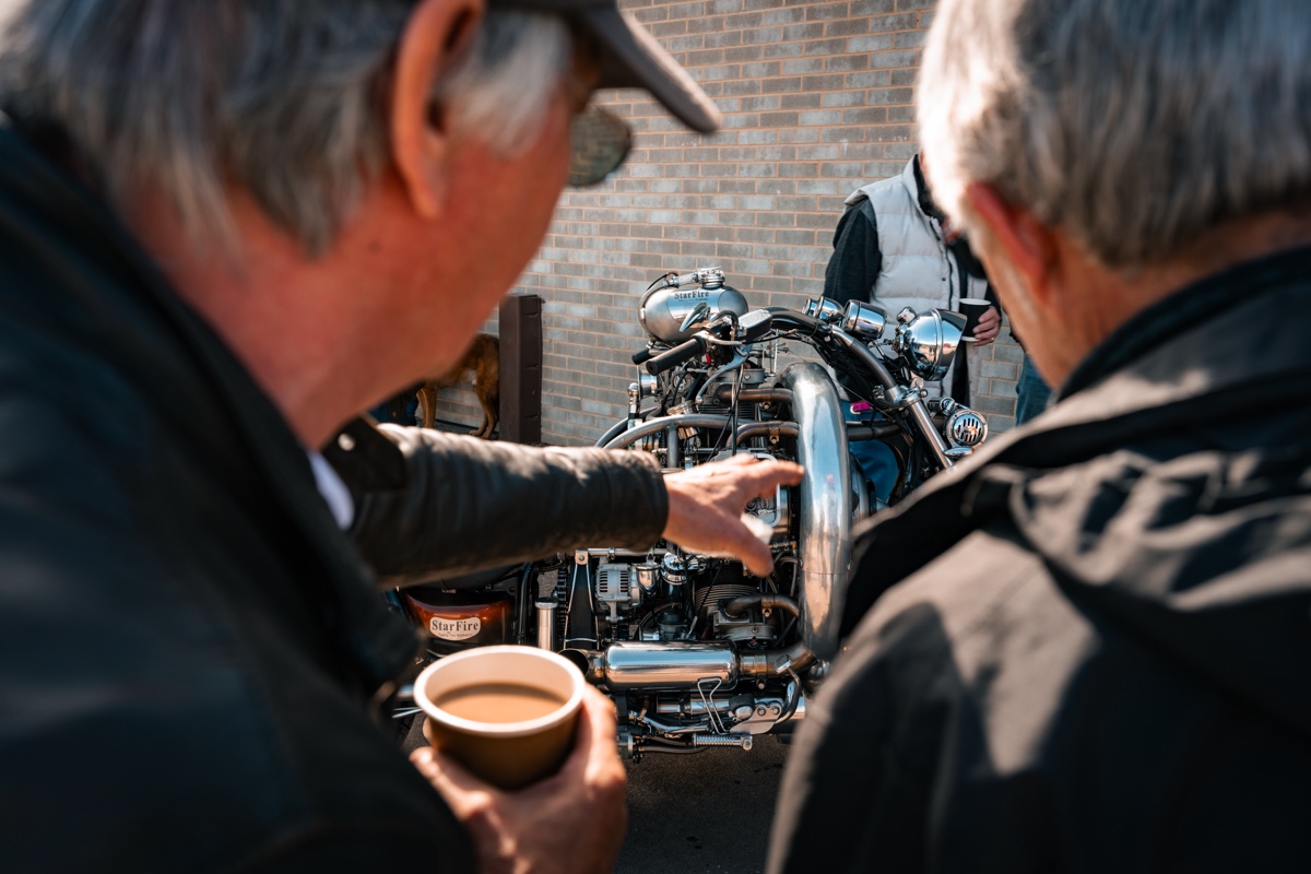
Indeed! What an incredible triumph of home-brewed engineering, pure persistence, and shared passion. We’re honored to showcase this machine and the story behind it. Below, you’ll find many more details of the build, along with snippets from our back and forth discussion with Tim about various aspects of the build.
Most of the photos are from our photographer photographer Roberto Garagarza (@roga______) at the 2026 KICKBACK Show, though a few of the lighter shots come from Chris Mabey (@classic-motorcycles) — a volunteer photographer for the Sammy Miller Museum.
Project StarFire: In the Builder’s Words…
The Bike
The engine ran remarkable well, so Cheryl’s Virago we cut in half and new frame tubes were mandrel bent and notched by hand with a Powerfile and Starrett hole cutters in the pillar drill, to form the new frame. The bike was jigged and bolted to the decking in the back garden and took around a year to get to a stage where the bike could be driven and tested.
The engine had to be raised up to position with the gearbox beneath it, to reduce the bike’s length. The CofG is obviously high but once moving, is very nice to ride, smooth, comfortable, stable in the wind and nimble.
Drivetrain
The engine is connected to a large bearing-mounted assembly, supporting a 3-inch Harley primary pulley, via a modified Ural sidecar cush-drive.
Gearbox/Clutch
The 1960’s Harley 4-speeder is belt driven by the engine, the output of which is reversed through a homemade gearbox (skeletonized with side windows ) to drive the rear wheel driveshaft and bevel box by chains and sprockets. Final gearing gives 70mph at approx. 2000rpm.
The 85-amp alternator is the tensioner for the main drive belt and runs backwards — no issue doing that, except slight reduction in cooling fan efficiency.
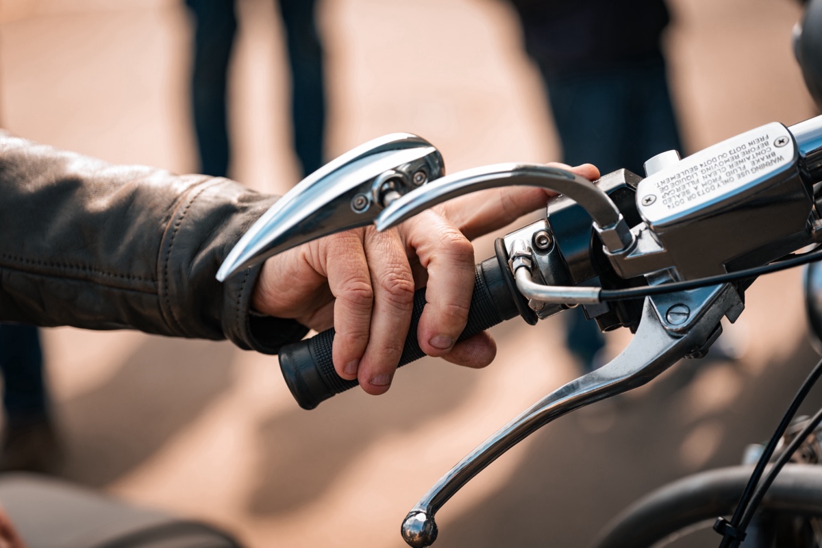
The “ratchet mechanism” of the Harley gearbox was removed and a hand-shift gear lever selects each gear directly, with no gates — you feel them in. Clutch is operated by foot pedal, a handlebar lever was retained.
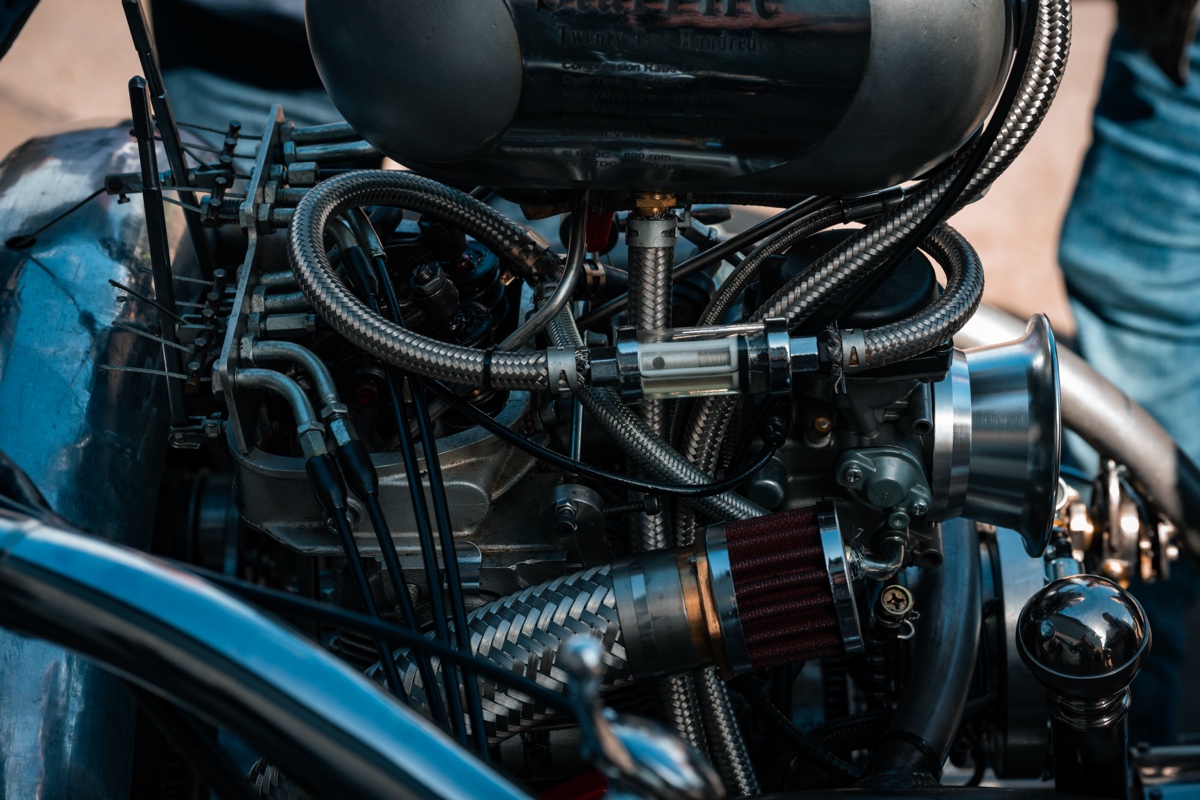
Fuel
The header tank is fed by fuel pumped from the main tank under the seat, gravity-feeding the five carbs and ten cables that operate the individual throttles and chokes.
Toolbox
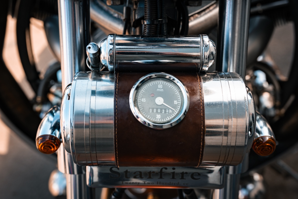
We took the original bike’s silencer box, turned it around and polished it up. The other end where exhausts pipes entered and exited, we cut out and made a polished ally end plate with key lock. Mounted under the swingarm, it carries some bespoke tools.
Electrics
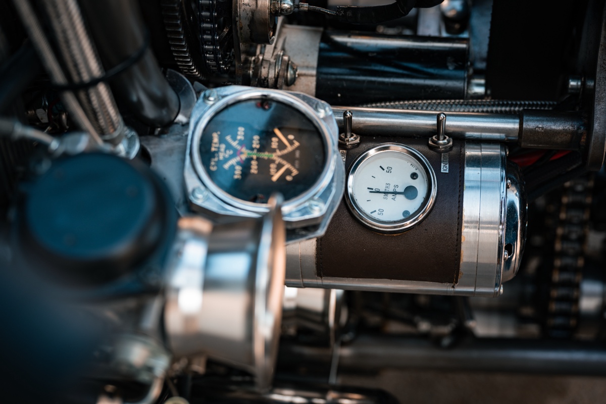
The engine’s own loom with several relays, runs down the left side of the bike to a distribution box (large diameter ally tube, part covered in leather with chrome horns fitted as end caps). An ammeter is fitted.
Yamaha handlebar switch gear was used, but the whole loom was binned except the ignition barrel and the small fuse box.
Homemade bike loom terminates in the headlamp and another distribution box as mention above, mounted on the forks, housing an engine “run time” hour meter, complimented by a vintage chrome car fire extinguisher.
Battery
ATOM-AGM-20-3 battery is pretty small but provides 20amp/hour and 250amp cold crank and has been awesome.
Ancillaries
Heat shields were rolled on a cheap purchased English (Chinese) wheel, a new skill to learn and challenge for us, great fun and humbling when you see the “pros.”
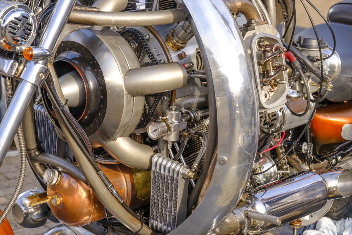
The scoop for the lower oil cooler (like a large radial engine intake scoop), was beyond our English wheel rolling capabilities to fabricate. A polystyrene and plywood mould covered in carbon fiber was made and chrome car vinyl wrap utilized.
Rev counter is a vintage handheld “lathe setters'” rpm gauge from yesteryear.
The Engine – General
Radials are remarkable engines, and the uneven movement described internally during rotation presents challenges not found in conventional engines, leading to ignition timing, cam timing and balancing issues requiring work-arounds. With this, along with the oil system design, the engine spent ten months in the front room while we overcame them.
Engine Construction
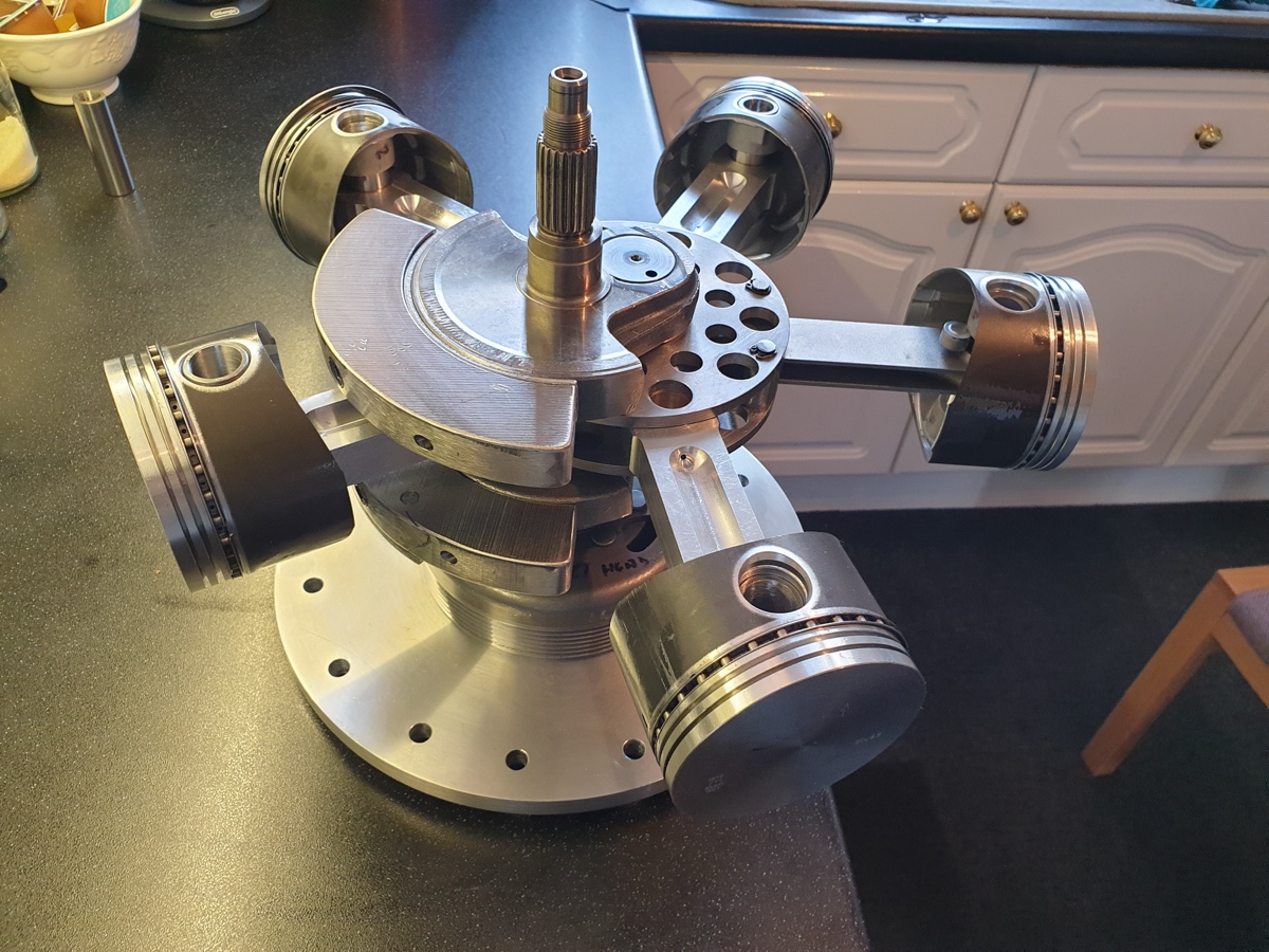
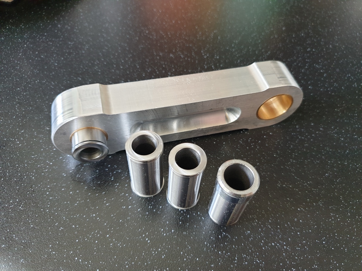
The master rod that holds the interconnecting rods is a very complex piece to make. It is very heavy (made from EN24T), and to reduce weight we machined the interconnecting rods (con rods) from ally, taking into account the thermal expansion in length for compression ratio variations.
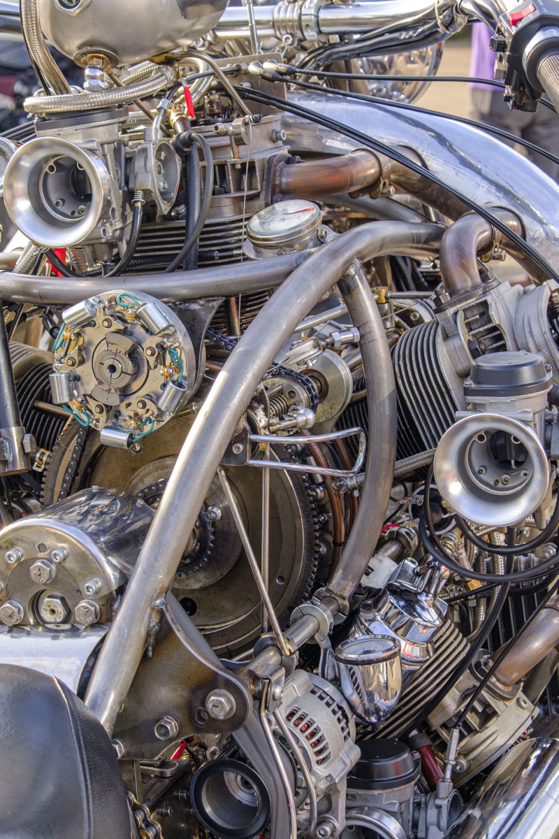
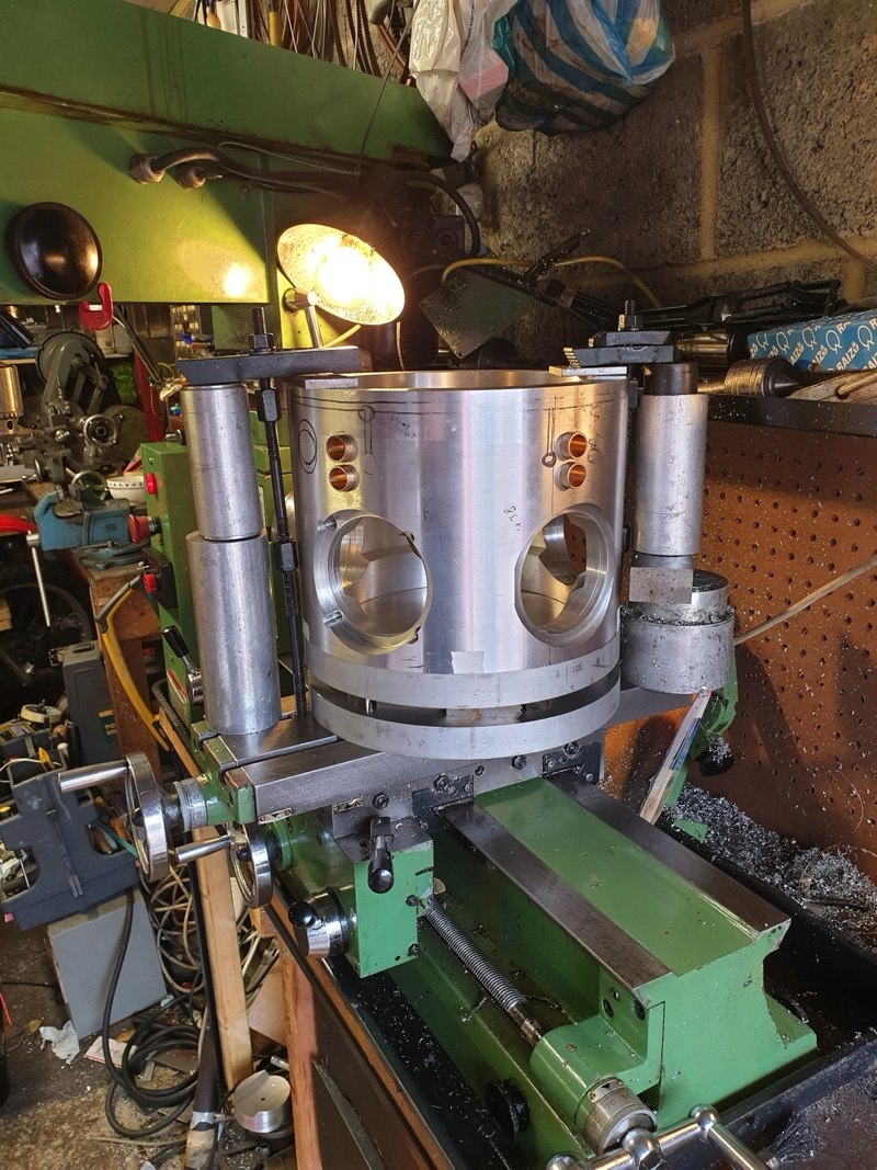
Crankcase is 11-inch billet ally bored out with internal lighting and viewing window revealing the five cams (XT500 cams cut in half, re-indexed and welded) within, when running.
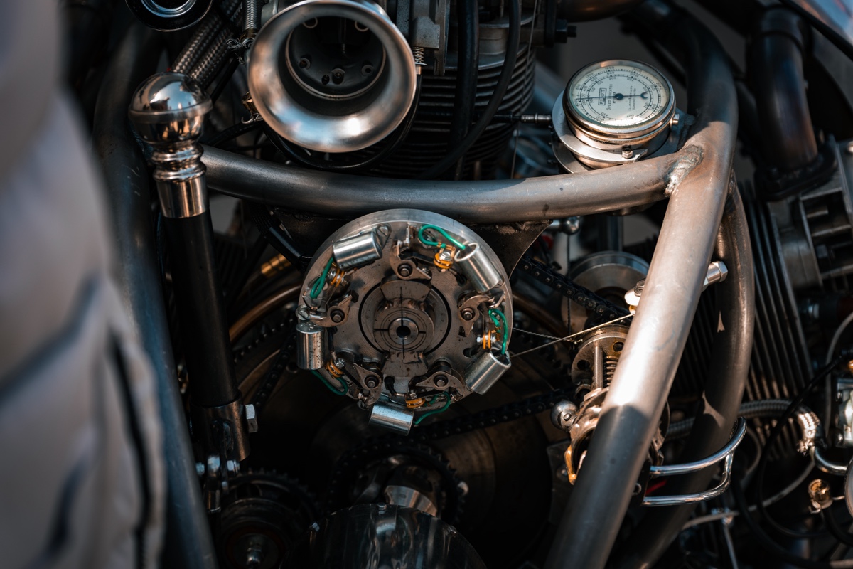
Cam chain and sprockets are exposed, as are the distributor/cooling fan/ignition advance chain and sprockets. Substantial balance weights were required and had to be fitted after the crankshaft/master rod was fitted in the crankcase, the balancing was quite involved.
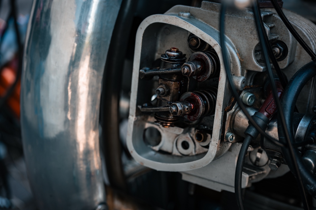
Valves and rockers are exposed, the two lower cylinders have decompressors on the inlet valves with drain cocks in the intake tract, to prevent hydraulic lock from any oil seepage past their piston rings, on start up.
In case of a stuck valve or broken decompressor cable, for safety, we “pull through” two revolutions after the engine has sat for a while, so we made a kick start. It is about twice the length of my XT 500 kicker.
Heads
The heads are VW “twin ports” cut in half with VW barrels and forged offset pistons.
Ignition
The ignition is wasted spark, the initial set up was the flywheel operating five sets of points (on a rotating plate for advance), triggering the five coils/condensors. Timing advance is by external bob weights. A low tension distributor operating five sets of points has now been fitted, making cleaning/adjusting of the points a breeze.
Cooling (Radials need a lot)
Cylinder fin cooling is by centrifugal fan running 2.5x engine speed through a sprag clutch. Additionally two side-mount oil coolers are fitted, supplemented by a third one at the bottom of the bike, oil being pumped separately via a stack pipe in the oil tank (a vintage copper garden sprayer), by way of an electric oil pump — so in case of stone damage, engine oil feed is maintained.
Oil Pump
Modified Kobota plant equipment item, belt-driven producing around 55 psi at 90 degs C and at a high flow rate. An 80psi pressure relief valve in the oil tank protects the pump and supplements a post oil filter pressure relief valve.
External Lubrication
All exposed chains: Wet chain spray lube is used and carried in a round ally container on right lower frame tube. The rocker shafts are bored out and the ends plugged and fitted with flush fitting (Zerk) grease nipples. Tappets get a blob of grease now and then. Valve stems get a drop of engine oil if they are really good! A mini grease gun is carried on right lower frame tube and an oil syringe in the chrome box on the lower fork yoke.
Technical Data
Cam timing at 0.050″ thou –
Inlet Open- 11 degs BTDC
Inlet Closed- 50 degs ABDC
Exhaust Open- 48 degs BBDC
Exhaust Closed- 17 degs ATDC
Tappet clearance – 0.012″ thou cold
Ignition Timing:
7 Degs BTDC -idle
30 degrees BTDC – 2500 rpm
Compression ratio: 7.3:1
Fuel consumption: 20mpg
- Bike: Virago XV750
- Wheels and brakes/forks/shocks/shaft drive/bevel box: XV 1100
- Fuel tank/speedo/switchgear/footrests: XV535
- Headlight: XV535/visor from a larger light cut and bonded on
- Cooling fan: VW Beetle
- Toothed drive belts sourced from China
- Electric oil pump: Mocal EOP2 back axle oil cooler pump
- Control Cables: handmade
- Oil/Fuel pipes solid and braided: handmade (Vibrant Performance Hose Cutting Shears are awesome if making braided pipes)
- Silencers: 4.5 inch polished stainless 12″ long (myriad-exhaust)
- Handlebars: Harley Beach style, extended
- Gauges (oil px/temp, ammeter, voltmeter): Aftermarket tractor gauges
- Ignition coils/condensors: Rex’s Speed Shop
- Tail light assembly: Beedspeed
- Fuel Cap: Hiyoyo chrome quick release.
On tooling and early engines…
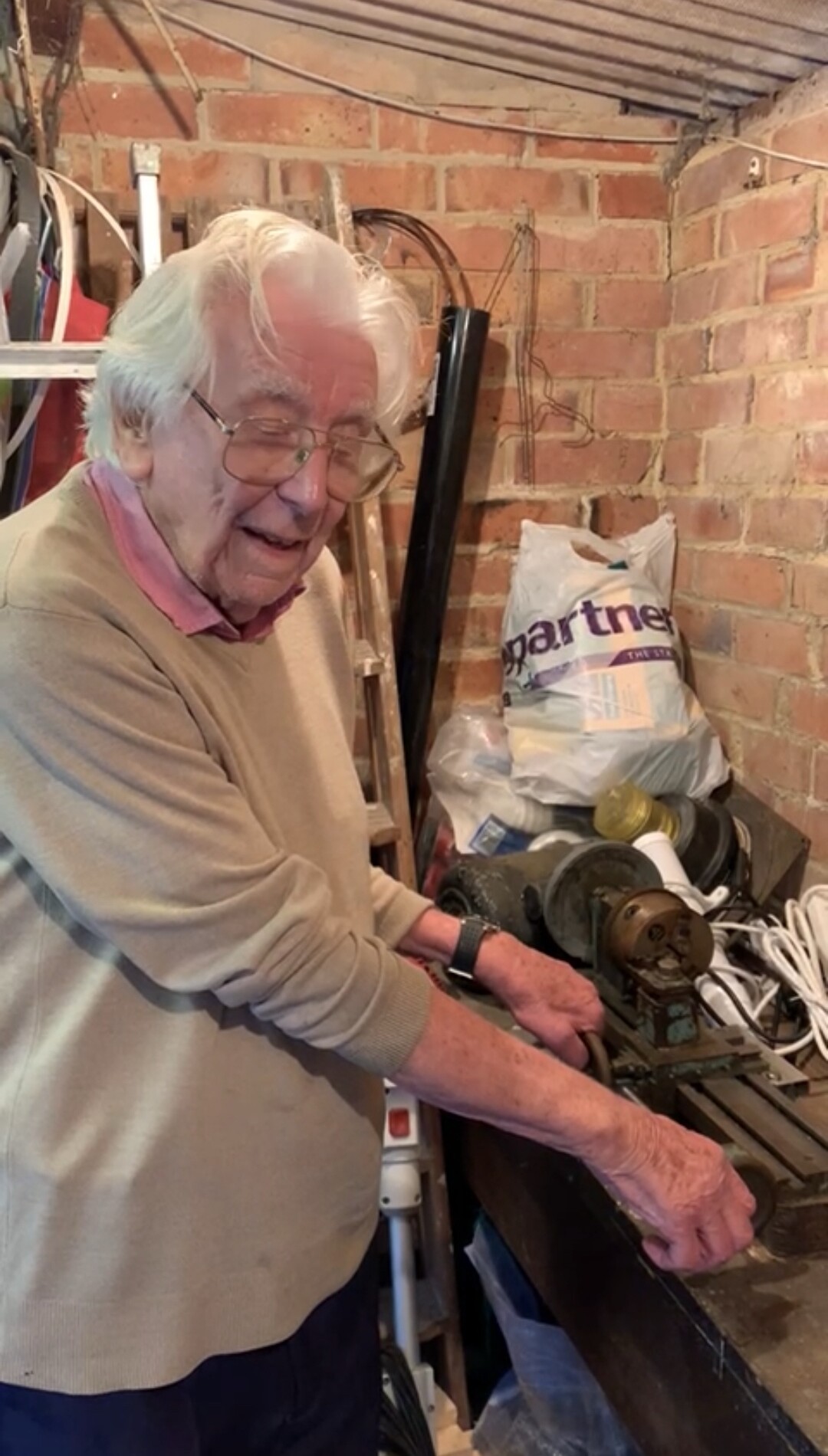
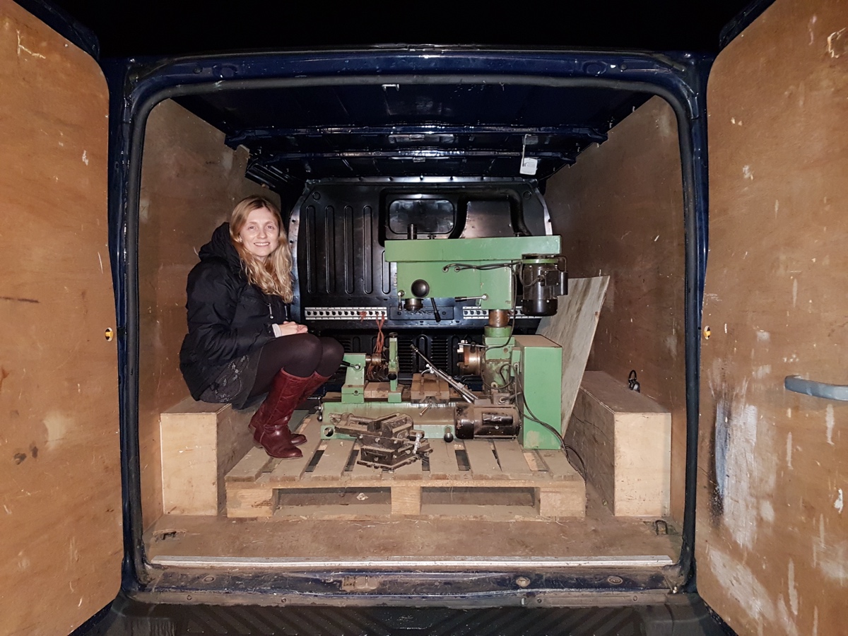
Tooling was very simple. We had to buy another second hand lathe to take the crankcase for machining, which we won on eBay. We have a standard Myford that some of our other engines were built with, but in the beginning everything, including our early jet engines, were built on Dad’s homemade lathe (picture of Dad in his mid nineties with his homemade lathe).
Dad made it in the early 1940’s with materials he acquired from scrap bins. In the late 80’s I stiffened the headstock and added a better cross slide, but the tail stock remained the same, a sliding bit of bar knocked onto a chuck that you leant on with a piece of wood.
The jet engine took around six years to get it reliable and flying in our model plane, which became our main focus for many, many years. Our first engines we built were flame engines which run on flames. The first piston engines made were of low power output and temperamental, but great fun.
Then we made hot air engines (Sterling engines) and also got into steam locomotives, a scale 3.5 inch model of the “Evening Star,” which we resurrected from the ashes and runs beautifully.
We use G clamps and lumps of wood, cut everything by hand with a hacksaw and I don’t do drawings, just draw on a piece before machining. We do everything by eye and do not possess precision diving heads etc, just eyeball and a pair of dividers. Everything is a challenge to overcome and satisfying when you eventually get there.
I use a gas brazing torch for silver soldering and brazing, and with the right flux, you can virtually weld anything together. We borrowed my son’s MIG welder to make the motorbike frame. The critical parts of the headstock, a friend Marcus, a professional welder, TIG-welded for me. He also did the final welds on the camshafts and the main drive sprockets and helped press the crankshaft together with me, an amazing guy.
On overcoming obstacles…
With large projects, you have to move on, it is so easy to get bogged down on a challenging engineering issue and usually the solution is basic and simple. There were many of these issues when you make an engine, or a gearbox or a bike for that matter and many sleepless nights and worries ensued, but grabbing the problem and just going for it, usually pays off.
One of the biggest challenges was when we pressed the crank together, I had made the crank pin a 0.005 thou interference fit. Our cheap hydraulic pressure peaked at 10 tons and despite freezing the pin and heating the webs, the pin jammed half way. Our local engineering shop has a seriously old press that I had to use in the end.
12.5 tons was required and many small pressing operations were conducted with measurements of run-out being checked each time and brutal adjustments with the largest copper hammer I could buy, being made each time, to arrive with a crank runout of about 0.0015 thou each end, a massive move forward and overall relief when that was accomplished.
The master rod assembly…
The master rod assembly that holds the interconnecting rods was the hardest part to make. This is what separates a radial engine from a normal engine. The whole engine rotates on just one crank pin. The forces are huge. A normal 4-cylinder engine would have four big ends — we don’t, we have one.

The main conrod of our number one cylinder is fixed to a round “cotton reel” assembly if you like. The cotton reel has 4 pins in it, which carry the other interconnecting rods (con rods). The poor old number one cylinder stops the cotton reel from rotating around the main crank pin and guides all the other con rods. As the number one piston goes up and down, it is being smashed sideways in the bore, every time another cylinder fires. It has a brutal life.
Because of the unusual movement the master rod creates inside, no cylinder reaches its top dead center position when it should. For this reason, each cylinder has to have its ignition and valve timing adjusted individually to suit.
Preventing hydraulic lock…
Hydraulic lock is a real concern on the lower cylinders and so the engine was fitted in the configuration it is now, so only two cylinders are inverted instead of three. In aircraft engines, oil control ring lands on lower cylinders can have no holes to stop oil weeping past the rings and some inverted engines have five piston rings to hold the oil back.
We overcame this problem by fitting valve lifters on the inlet valves of the two lower cylinders and a drain cock in each of there respective intake manifolds. This saves removing spark plugs and clearing any oil weeping through over days of inactivity. We are lucky in that with the bike on its side stand, any oil weeping past the rings misses the spark plugs and exits without fouling them, very lucky.
Transmission and gearing…
The engine drives a 1960’s Harley 4-speed unit, the output we have to reverse to eliminate the torque reaction when riding, and I found some secondhand Norton gearbox shafts. Unfortunately after making the gearbox I found one of the shafts was bent and couldn’t find that shaft again so had to grind up a different shaft to suit, a setback but it worked out okay. Several different sprockets and changes to gearing had to be made to arrive at what I wanted, 70mph around 2000rpm and fuel consumption is around 22 to the gallon.
Finding an oil pump…
To speed up things, the oil system was powered by an electric oil pump and was okay for test bed tuning but not under load in the bike. As far as I can see, car mechanical oil pumps have plain bearings and leakage into the sump is provided at each end for lubrication and cooling. We needed vastly greater oil flows and pressure so I found a Kobota diesel engine oil pump which has worked well for us.
It needed modification to both shaft ends to prevent leakage. The rear bearing is easy with a simple plate but the front drive sprocket end is not. Machining an O-ring groove would reduce bearing contact surface too much, so a half radius was machined in the front case and a small end plate bolted to the front casing with a matching half radius machined in it to take an O-ring — simple but effective.
Fighting vibration…
Radial engines have their own “natural beat” when running, which is unusual. We found that at between 60 and 70mph under load we get some vibration. It felt like a misfire and we tried everything to overcome it. I built a simple plywood plate with five switches on it, to switch off each cylinder at 60mph to identify which cylinder might have an issue, to no avail.
I opened up the fuel lines in case the carb float bowls were not filling quick enough, nothing helped. We altered ignition timing, valve clearances, everything really. Because we were limited in size in the workshop, the conrods are a lot shorter than I wanted, so our piston speeds are higher and hence our secondary balance is poor. It all added up to us accepting it is a natural design condition, but we also have no idea what the oil is doing in the cylinders at these speeds. The engine is going round 33 times every second (2000rpm) and the oil could be pooling in the lower cylinders and unbalancing the engine.
I found a vintage dynamic balancing machine on eBay, which I resurrected. It uses a strobe, fired by a transducer which signals the control box at maximum amplitude, but needs a lot of tinkering and adjusting to get results. We managed to improve the vibration a little, but we have just made a dynamic balancer last week and mounted it to a flywheel. Basically a circular tube containing fourteen 10mm steel ball bearings that naturally dynamically balance the engine.
It has worked and engine is smoother. It is just the initial test stage, but promising. It is like in the old days where tyres were balanced on cars with beads thrown inside them.
Cheryl — the secret weapon…
Cheryl was not only involved in the whole engineering and design of the engine and the bike, but has a super keen eye and identifies problems and failures as they occur; she is invaluable in this respect and excelled during the valve timing side of things with a memory for differences in valve opening and closing events that we had to design out as we progressed. She also found an old WW2 paper on radial engine balancing, which was invaluable.
How the bike rides…
The bike rides very well indeed very comfortable and I am very used to it now. There is so much going on with valves and distributor operations coming together to propel the machine along, with oil pumps keeping everything alive and the engine whizzing around in a confident yet slightly unusual beat that radials have, it always feels like you have been on an adventure when you arrive at your destination.
It’s like we took on a challenge and together we all pulled it off. We have ridden on the coldest days through the winter and the hottest days in the summer and she has never missed a beat.
When we pull up it is wonderful to chat to people. We get many questions, especially about how hot it must be behind the engine, but there is no noticeable heat there. Only your right leg gets warm if you put it directly in the exhaust, the left exhaust is actually cool, yes it’s cool. There is no vibration damping at all on the foot pegs or handlebars — doesn’t need any.
It is great to ride with the foot clutch and the hand change, it really makes the whole experience unique; it is intuitive and adds just a little something different. My father rode foot-clutch Indians and I wanted to add that as a nod to those amazing riders of yesteryear.
Tim’s father’s involvement…
My father, an incredible engineer, saw the whole project through and it was the greatest honour for me to take him on his last ride out on StarFire to his final resting place, she did us proud! [You can see Tim’s father watching in the video below.]
Other issues that arose…
We did have issues during the build. Whilst pressing the cam lobes onto their shafts, I had one shatter on me. Since then I wear a full face crash helmet when pressing anything together.
I was sliding a sprocket onto a shaft I had just made, by hand, and it locked up, cold welding itself together. I was aware of galling, but this was exceptional and required tons of hydraulic pressure to press apart destroying the shaft. Very strange.
Looking back at the process…
It is strange that when I started writing something down, a lot comes back to you. We have sort of forgotten the skinned knuckles, sleepless nights and many burns over the years 😀. It is a creation that will need constant work and we are still developing things.
Your passion is amazing and a credit to you offering an insight into a world that exists beyond the normal offerings from the big brand motorcycle manufacturers.
Follow the Builder
YouTube: @tim777jet


If Chitty Chitty Bang Bang had been a motorcycle instead of a car.
Such an ambitious realization of a wonderfully odd flight of fancy. And epic problem-solving skills. Bravo and brava!